05. FMCW Hardware and Antenna
FMCW Hardware
L1A40 Antenna
FMCW Hardware Overview
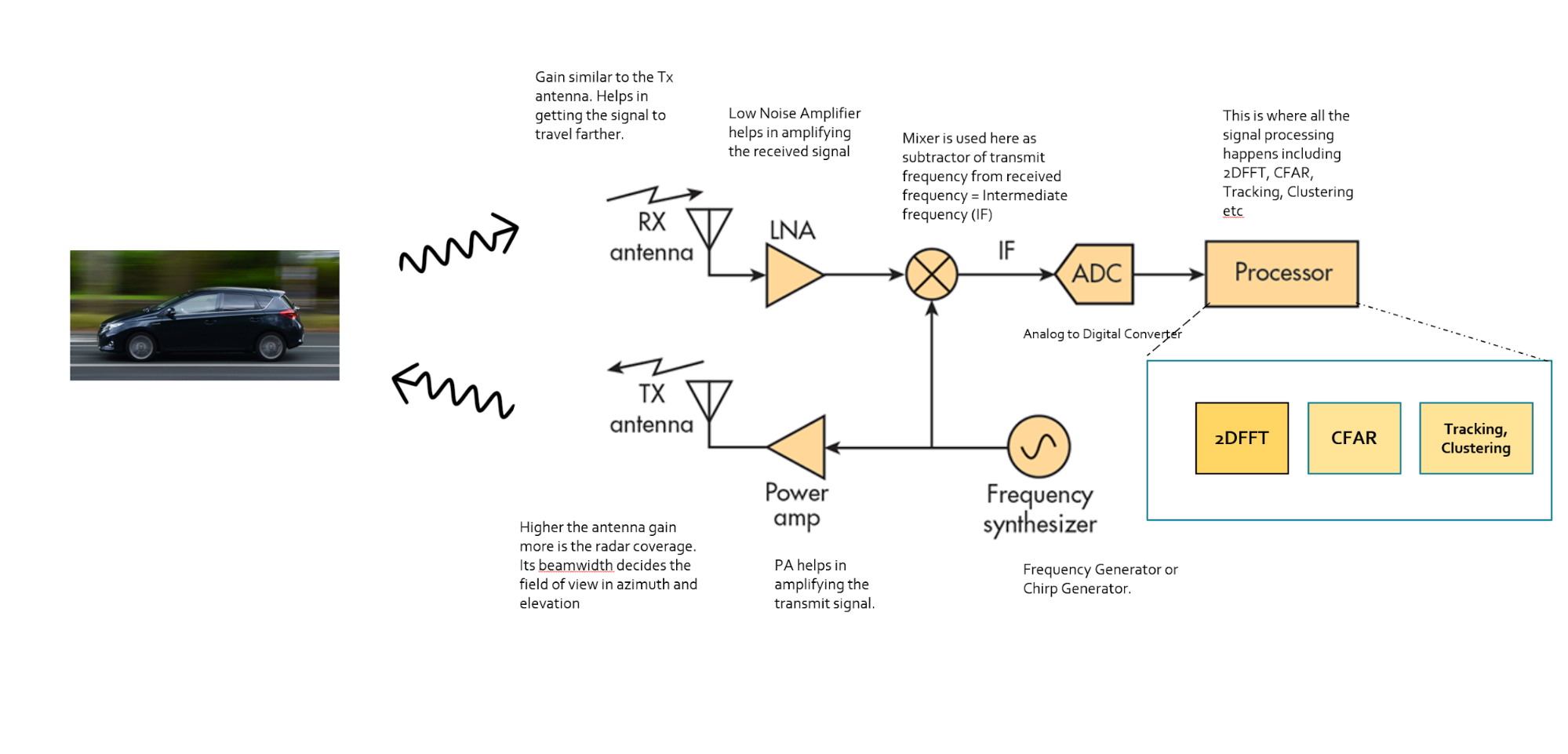
Hardware implementation of the FMCW Radar
Frequency Synthesizer : The frequency synthesizer is the component that generates the frequency to bring the chirp frequency all the way to 77GHz in case of automotive radar.
Power Amp : The power amp amplifies the signal so the signal can reach long distance. Since the signal attenuates as it radiates, it needs higher power (amplitude) to reach targets at greater distances.
Antenna : The antenna converts the electrical energy into electromagnetic waves which radiate through the air, hit the target, and get reflected back toward the radar receiver antenna. The Antenna also increases the strength of the signal by focusing the energy in the desired direction. Additionally, the antenna pattern determines the field of view for the radar.
Mixer : In FMCW radar, the mixer multiplies the return signal with the sweeping signal generated by the frequency synthesizer. The operation works as frequency subtraction to give the frequency delta - also known as frequency shift or Intermediate frequency (IF). IF = Synthesizer Frequency - Return Signal Frequency.
Processor : The processor is the processing unit where all the Digital Signal processing, Detection, Tracking, Clustering, and other algorithms take place. This unit could be a microcontroller or even an FPGA.
Antenna Details
L1A40 Antenna
Antenna Property
As defined in the FMCW Hardware definitions, the antenna is a transducer that converts the electrical energy into electromagnetic waves. In the case of radar, these waves travel through the air and hit the target. Depending on the surface type and shape of the target, the waves get partially reflected back in the direction of the radar. The receiver antenna at the radar amplifies the received signal further and sends it to the receiver chain for further processing.
The Antenna Pattern
Radar Antenna Pattern
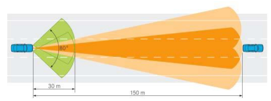
Radar illumination on the road scenario
source : sciencedirect.com
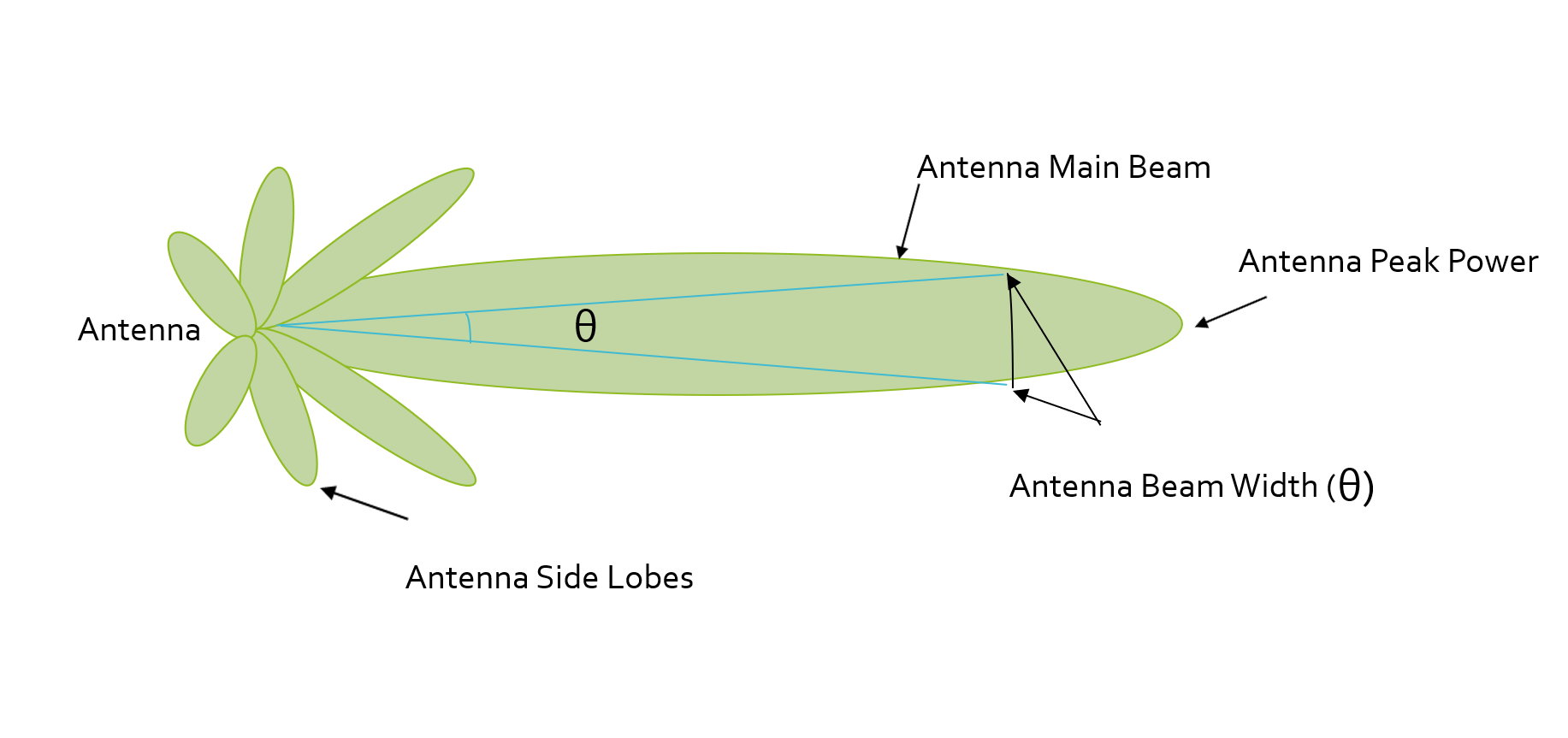
Antenna Pattern
The antenna pattern is the geometric pattern of the strengths of the relative field emitted by the antenna.
The beamwidth of the antenna determines the field of view for the radar sensor. If the requirement for the radar is to just sense the targets in its own lane then the beamwidth needs to be small enough to cover the complete lane up to desired range. If the beamwidth is wider than the lane width, it will sense the targets in the other lanes as well.
Antenna Pattern
Antenna Sidelobes
Antenna radiation not only comprises of the main beam but the sidelobes as well. Antenna sidelobes are critical because they can generate false alarms and pick interference from undesired direction. As seen in the pattern, the sidelobes of the antenna point in different directions and can sense targets that are not in the main beam. To avoid sidelobe detections it is critical to suppress the sidelobe levels to more than 30dB from the peak of the main beam.
Antenna Types
]](img/image14.png)
There are many types of antenna (dipole, patch, horn) that can be used at 77GHz, but the most commonly used antenna type in automotive radar is the patch antenna . The low cost, easy fabrication, and low profile of Patch Array Antennas makes them an ideal choice for automotive radar applications.
ND313 Andrei Intv 19 What Do Radar Antennae Do
Antenna Quiz
SOLUTION:
- A stronger main beam (peak output power) is used for Long Range Radar (LRR).
- A narrow Beamwidth is used for covering fewer lanes.